Even if it becomes less and less common years after years, there are still some devices in audiovisual pro that are controlable through serial port (RS-232, 422, 485). It allows very efficient and precise control of devices, and also if needed feedback of devices for a stable control.
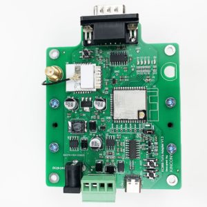
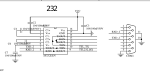
Main problem is to find an interface for physical interface with devices controlled. One easy and logical solution is to use ESP, tha allows a lot of flexibility for interface. Unhappy ESP works with 3V3 logical level while serial ports such as RS-232 use voltages between -25V and +25V at maximum, which is completely incompatible with ESP. Direct connection of a serial RS-232 port with ESP GPIO would destroy immediately the ESP ! It is mandatory to use an interface between the ESP and serial port with an electronic circuit such as MAX232 from Maxim that will do the logical conversion of electrical levels. An other easier solution is to use an all build board, like for example, the Tuya Adapter (Less than 20 bucks on Aliexpress) made by Kincony.
 |
 |
The board has been designed at first to interface with Tuya equipments but we are going to use it as RS-232 or RS-485 interface (depending of a jumper on the board). To power the board it can be done easily using either the standard round power connector or through the Phoenix one. RS-232 connection is done through the sub-d9 and RS-485 on the Phoenix connector.
We need now to prepare an ESPHome sketch to overwrite the existing manufacturer firmware and be able to integrate it easily in Home-Assistant.
Configuration is going to be quite simple and I’m going to share 2 use cases. First we’ll start with control of a Meridian Audio Processor. Protocol supplied by manufacturer is avalaible on this link. First thing we need is communication parameters: for a serial link it implies speed in bauds, stop bit, and parity. In protocol document it’s indicated 9600 bauds, 1 stop bit and no parity. We get luck, it’s nearly default ESPHome settings for serial port so we’ll just need to configure speed at 9600 bauds.
For wiring we just need to connect 3 wires: RX, TX and GND (Ground). Depending of devices, RX and TX will need to be crossed or straight between Kincony and device controlled (no scientific rule about crossing or not !).
We need now to determine syntax of “messages” for control of the device. Protocol indicates we need just to send 2 characters sometimes with an extra argument and ends with “Carriage Return”. We’ll just need to put that string in uart.write command in ESPHome code. Carriage Return is an invisible character that encodes the return at begin of line, it’s most of time encoded as CR or here for ESPHome with the escape characters so: \r . It’s quite common that commands are ended by CR or LF (Line Feed) or both. Here programmer by default has included both in code.
For example to switch Meridian processor on TV input, command will be: TV\r\n
esphome:
  name: esp-meridian
  platform: ESP32
  board: esp32dev

logger:

web_server:

ota:

wifi:
  networks:
  - ssid: !secret wifi_ssid
    password: !secret wifi_passwd

captive_portal:

api:
  reboot_timeout: 10min

button:
  - platform: template
    name: Meridian CD input
    on_press:
      - uart.write: "TV\r\n"
      - delay: 1s
      - uart.write: "VN90\r\n"
      - delay: 20s
      - uart.write: "VN90\r\n"
  - platform: template
    name: Meridian DV input
    on_press:
      - uart.write: "DV\r\n"
  - platform: template
    name: Meridian Stanby
    on_press:
      - uart.write: "SB\r\n"

switch:
  - platform: template
    name: Meridian Audio Direct
    id: direct
    optimistic: true
    restore_mode: restore_default_off
    internal: false
    on_turn_on:
      - uart.write: "PN0\r\n"
      - switch.turn_off: cinema
      - switch.turn_off: music
      - switch.turn_off: thx
  - platform: template
    name: Meridian Audio Cinema
    id: cinema
    optimistic: true
    restore_mode: restore_default_off
    internal: false
    on_turn_on:
      - uart.write: "PN12\r\n"
      - switch.turn_off: direct
      - switch.turn_off: music
      - switch.turn_off: thx
  - platform: template
    name: Meridian Audio Music
    id: music
    optimistic: true
    restore_mode: restore_default_off
    internal: false
    on_turn_on:
      - uart.write: "PN1\r\n"
      - switch.turn_off: cinema
      - switch.turn_off: direct
      - switch.turn_off: thx
  - platform: template
    name: Meridian Audio THX
    id: thx
    optimistic: true
    restore_mode: restore_default_off
    internal: false
    on_turn_on:
      - uart.write: "PN13\r\n"
      - switch.turn_off: cinema
      - switch.turn_off: music
      - switch.turn_off: direct

uart:
  tx_pin: GPIO17
  rx_pin: GPIO16
  baud_rate: 9600
In this second case, we are going to control a Loewe TV that has a serial port on RJ-11 connector (quite unusual connector for RS-232). Protocol supplied by manufacturer is avalaible on this link. We are going to use same logic as previously.
For serial port parameters, we are in same configuration.
For commands to send, we are in quite similar case. Little change here, we are going to control volume which implies to send values in a dynamic way to device. Using lambda, we’ll be able to build dynamically string to send at TV (“data volume XX” with XX being volume level requested). Value will be stored in a local variable in ESPHome that’ll be avalaible directly in HA so we can adjust volume as we wish (common use is with a bargraph).
esphome:
  name: esp-tv-loewe
  platform: ESP32
  board: esp32dev

logger:

web_server:

ota:

wifi:
  networks:
  - ssid: !secret wifi_ssid
    password: !secret wifi_passwd

captive_portal:

api:
  reboot_timeout: 10min

button:
  - platform: template
    name: TV HDMI1
    on_press:
      - uart.write: "prog -6\r\n"
  - platform: template
    name: TV HDMI2
    on_press:
      - uart.write: "prog -7 \r\n"

switch:
  - platform: template
    name: "TV mute"
    optimistic: True
    turn_on_action:
      - uart.write: "data mute 1\r\n"
    turn_off_action:
      - uart.write: "data mute 0\r\n"
  - platform: template
    name: "Power tv"
    assumed_state: True
    optimistic: True
    turn_on_action:
      - uart.write: "power tv\r\n"
    turn_off_action:
      - uart.write: "power off\r\n"

number:
  - platform: template
    name: "TV Volume"
    id: test
    optimistic: true
    min_value: 0
    max_value: 95
    step: 1
    on_value:
       - uart.write: !lambda
                      char buf[128];
                      sprintf(buf, "data volume %.1f\r\n", id(test).state);
                      std::string s = buf;
                      return std::vector( s.begin(), s.end() );

uart:
  tx_pin: GPIO17
  rx_pin: GPIO16
  baud_rate: 9600
Few key points to get your serial control working:
- wiring between controlled device and ESP board might need to reverse RX and TX (depending of devices wiring will need to be straight or crossed !). Wiring will be done most of time on SUB-D9 but con be more exotic connectors such as RJ-11 for our Loewe TV.
- Be careful to configure properly speed, parity and stop bit (depending of protocol documentation from manufacturer).
- be able to get protocol documentation supplied by manufacturer (it’s impossible to guess control protocol if you are unable to get from manufacturer, each manufacturer has its own protocol that can even be different for different devices from same manufacturer).
Recent Comments